Your First Design
A hands-on tutorial to create your first parametric CAD design using Conjure.
Overview
In this tutorial, you'll learn how to use Conjure to create a simple but practical design: a customizable enclosure box with mounting holes and a lid. This will teach you the fundamentals of working with Conjure and AI-assisted CAD.
What You'll Build
Project: Electronics Enclosure
- Dimensions: 80mm × 60mm × 30mm (width × depth × height)
- Wall thickness: 2mm
- Four corner mounting holes (M3 size)
- Rounded edges for a professional finish
- Optional: Ventilation slots
This tutorial assumes you're using Claude, ChatGPT, or another AI assistant that supports Conjure's MCP integration.
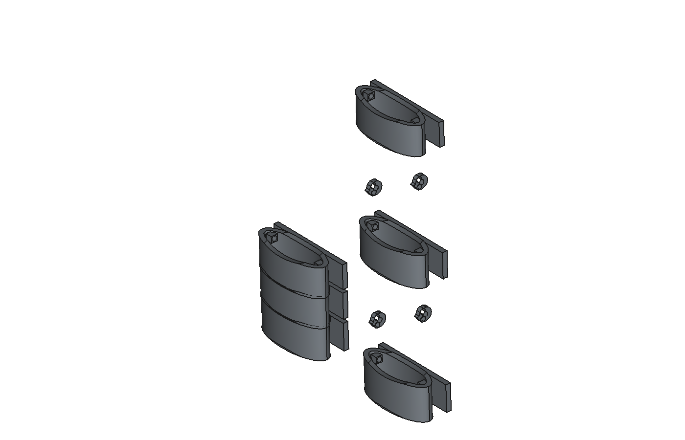
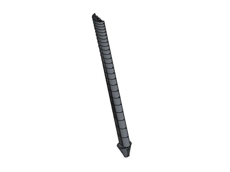
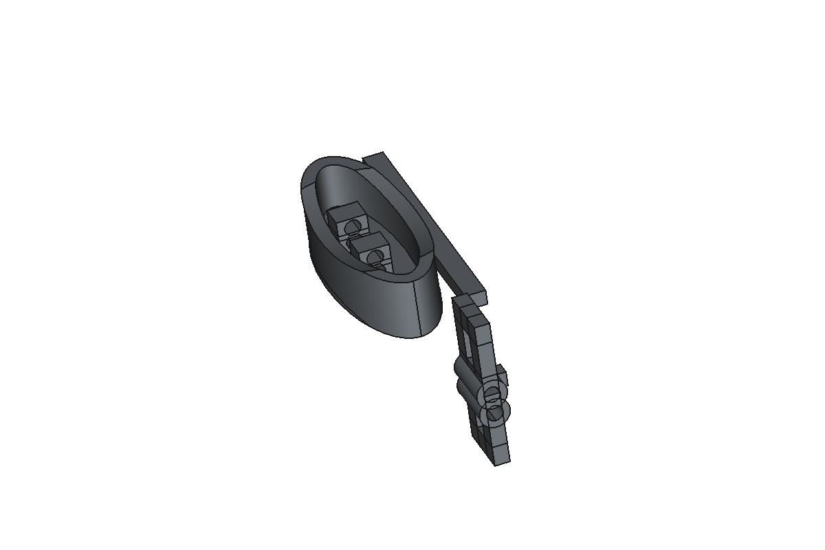
Here's what's possible with Conjure—from simple enclosures to complex multi-part mechanisms:
Step 1: Start a New Design
- Open your CAD software (FreeCAD or Fusion 360)
-
Create a new document/design
- FreeCAD:
File → New - Fusion 360:
File → New Design
- FreeCAD:
-
Switch to Conjure workbench (FreeCAD only)
- Click the workbench dropdown and select "Conjure"
- Verify connection: Check that the Conjure panel shows "Connected"
Step 2: Create the Base Box
Start a conversation with your AI assistant and ask it to create the basic enclosure:
# Creates outer box: 80 × 60 × 30 mm
# Creates inner cavity: 76 × 56 × 28 mm (accounting for 2mm walls)
# Subtracts inner from outer to create hollow enclosure
Step 3: Add Rounded Edges
Let's make the design more professional by adding fillets to the edges:
# Selects the 4 vertical outer edges
# Applies 3mm fillet radius to soften the corners
Step 4: Add Mounting Holes
Now let's add mounting holes in each corner:
# Creates 4 cylinders: 3.2mm diameter × 3mm height
# Positions:
#   - Corner 1: (5, 5, -1.5) mm from origin
#   - Corner 2: (75, 5, -1.5) mm
#   - Corner 3: (75, 55, -1.5) mm
#   - Corner 4: (5, 55, -1.5) mm
# Subtracts from main body
Step 5: Add Ventilation (Optional)
For electronics that generate heat, let's add some ventilation slots:
# Creates 5 rectangular slots per side (10 total)
# Each slot: 15mm × 2mm × 2mm (wall thickness)
# Left side slots at x = 0
# Right side slots at x = 80
# Vertical positions: 5mm, 10mm, 15mm, 20mm, 25mm from bottom
Step 6: Review and Refine
Take a moment to inspect your design:
- Rotate the view to check all angles
- Verify hole positions and sizes
- Check that walls are the correct thickness
- Ensure fillets are smooth and positioned correctly
If you need to make changes, just ask the AI. For example:
- "Move the mounting holes 2mm further from the edges"
- "Increase the fillet radius to 4mm"
- "Make the ventilation slots 1mm wider"
- "Add a small lip on the top edge for a lid"
Step 7: Export Your Design
Once you're happy with the design, export it for manufacturing:
For 3D Printing
Export as STL or 3MF format:
- FreeCAD: Select the body →
File → Export → STL Mesh - Fusion 360: Right-click body →
Save as STL - Via AI: Just ask "Export this design as an STL file"
For CNC/Professional Manufacturing
Export as STEP format (requires Pro subscription):
- FreeCAD:
File → Export → STEP - Fusion 360:
File → Export
Next Steps
Congratulations! You've created your first design with Conjure. Here are some ideas to continue learning:
Make a Lid
Create a matching lid that fits on top of your enclosure with a small gap for easy removal.
Add Cable Holes
Add cutouts for USB ports, power jacks, or other connectors on the side walls.
Internal Standoffs
Create mounting posts inside the enclosure to secure a PCB or component.
Parametric Variants
Ask the AI to create different sizes: "Make a version that's 100mm wide instead of 80mm"
Tips for Success
Be Specific
The more specific your instructions, the better results you'll get. Include dimensions, positions, and exactly which features you want to modify.
Build Incrementally
Start with basic shapes and add details progressively. This makes it easier to spot and fix issues early.
Use Visual References
Describe features in relation to visible elements: "the top face", "the front-left edge", "the outer surface". This helps the AI understand exactly what you mean.
Don't Hesitate to Iterate
If something doesn't look right, ask the AI to adjust it. You can undo operations or start over if needed. Experimentation is part of the design process!